
Microcrystal positioning method
(due to) A. van Donkelaar, CSIRO Health Sciences
SYNOPSIS: A superior, non-optical method for centralising protein crystals of less than 0.1mm diameter on the beam axis for microbeam crystallography
The adoption of a microbeam for protein crystallography in the laboratory permits the use of a crystal-centring technique previously unavaliable using large (0.3mm - 0.5mm) beams. The closer match of beam size to specimen size results in a larger fraction of the beam being intercepted by the specimen, in many cases with sufficient X-ray diffraction/absorption loss compared to the surrounding liquor for the presence of the crystal in the beam to be discernable by a 'dip' in transmitted X-ray flux as measured by a radiation meter placed downstream of the specimen. For example, using the 0.1mm-beam produced by the PX50 optical system and a Rigaku/MSC pin-diode flux meter, a 50-micron average diameter crystal of plant protein frozen in a cryoloop produces a ~10% dip in intensity when centred in the beam.
The following method assumes that the oscillation axis has been centred on the beam axis previously. This method is primarily intended to ascertain the presence of a specimen in the beam after a failure to observe a diffraction pattern. The observation of an absorption dip from the specimen with the subsequent absence of a diffraction pattern indicates a poor specimen.
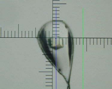
Method: Before placing the specimen on the goniometer head (if possible) and with the X-ray shutter closed, swing the beamstop out of the beampath and position the pin-diode on the outgoing beam axis away from the coldstream. Open the X-ray shutter manually from the generator control panel and ascertain that the pin-diode is registering the expected beam intensity, then close the X-ray shutter. Position the specimen on the goniometer and freeze it in the coldstream and centre it optically using the specimen telescope as normal. Finally, rotate the oscillation axis to place one translation of the goniometer head across the beam, then ensure that the cryoloop is oriented perpendicular to the beam axis by rotating the cryoloop base. Do not adjust the oscillation axis lateral position.
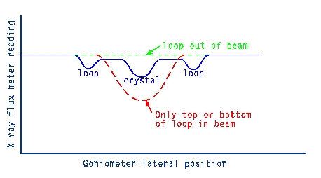
Open the X-ray shutter manually from the generator console. Select a scale on the pin-diode meter which gives the largest scale reading without pegging the indicator needle at the end of the scale. Slowly adjust the lateral goniometer head translation while observing the pin-diode meter, looking for one of the following behaviours:
 |
 |
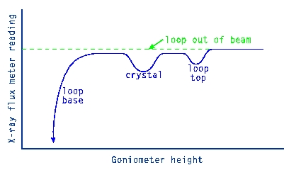
Note: if the crystal is not well-centred in the cryoloop, its absorption dip will occur nearer one of the loop edges and may not be resolvable from the dip associated with the cryoloop nylon twine. In this case, one side of the loop should produce a markedly larger absorption dip than the other. If it is suspected that the crystal is not in the beam at any point, centre the goniometer head translation (i.e. halfway between the cryoloop dips) and adjust the goniometer head height while observing the pin-diode meter for the following behaviour:
 |
 |
If the crystal is visually seen not to be well centred in the loop then it may be found by biasing the position of one adjustment appropriately and scanning the other while looking for the absorption dip. Finally, after centring the crystal in the beam, replace the beamstop and then use the pin-diode meter to ascertain that it also remains well centred.
(c) Copyright AXCO 2004